
BLOG
Industrial 3D Printed Tooling: Applications, Materials, and Design Considerations
Industrial tooling is no longer limited to machined aluminum or steel. Discover how additive manufacturing supports composite molds, production fixtures, and high-performance tooling across modern manufacturing.
By Ben Toomey
July 23, 2026
Tooling supply chains are constrained by escalating raw material costs, changing trade policies, and a shrinking toolmaking workforce. Often times, months go by waiting for composite layup molds, thermoforming tools, and production fixtures before a single part is produced. As manufacturing leaders look to compress production timelines, industrial 3D printed tooling has emerged as a viable alternative to legacy mold and fixture fabrication. By leveraging advanced 3D printed molds and custom fixtures, industrial operations are no longer bound to weeks of CNC milling and waste. Instead, manufacturers can deploy high-performance rapid tooling solutions in a matter of days.
Large format additive manufacturing (LFAM) has begun to emerge as a practical alternative and complement to legacy toolmaking. Rather than machining tools entirely from stock material, manufacturers have the agile capacity to produce near-net shape molds and tooling structures in a matter of hours before applying convergent machining and inspection processes. Overall maturity in the LFAM tooling space has accelerated how tooling reaches production.
The Case for Rapid Tooling
Conventional tooling requires significant investment before production. Material must be sourced, design made compatible, machining capacity scheduled, and finishing completed before the first article is ever produced. For most, tooling dictates the schedule long before the production line does. Add in ever-changing raw material costs due to trade policies and resources allowances and tooling costs become prohibitive, extending lead times as well.
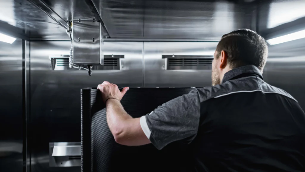
The approach with LFAM offers a different path for value, largely when requirements change throughout development. Design revisions that would normally require additional machining cycles can often be incorporated into a revised print with less disruption to the production schedule.
This shift has become broadened over time and landing itself at the heart of tooling processes. Composite molds, thermoforming tools, and assembly fixtures are now being routinely produced with large format systems across all sectors. Manufacturers can rapidly iterate a production tool, test the geometry sooner, or create a durable tool for a limited run. If demand grows or requirements stabilize, the experience gained from the printed tool can inform the next asset investment in production.
3D Printed Tooling Applications
Composite Molds and Layup Tools
Composite manufacturing is one of the most established uses for large-format printed tooling. Near net printed and post-processed molds can support fiberglass or carbon-fiber layup processes while reducing the sheer amount of scrap associated with stock material that would otherwise be machined down. Large contours and application-specific geometries can be directly designed into the mold.
For room temperature (or oven cured) applications, a machined and sealed thermoplastic tool provides the required surface and vacuum integrity. All areas of the mold process, being the selected material, infill structure, coating system, and curing procedure must still work together.
High Temperature and Autoclave Tooling
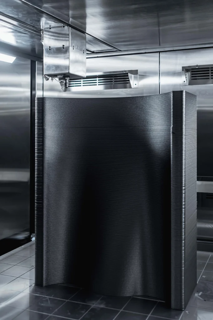
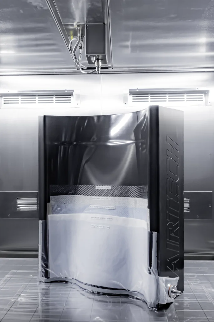
[Left: As-printed ULTEM tool in JuggerBot 3D Tradesman Series™ P3-44 Chamber. Right: Machined, finished, and demo-bagged 3D printed autoclave tool]
Autoclave tooling ability differentiates printer usage by raising the amount of stress and optimal application upon the part. The tool must tolerate elevated pressure and heat while mitigating geometry altering effects like the Coefficient of Thermal Expansion (CTE). Being able to reliably process high-temperature reinforced thermoplastics, such as PEI/ULTEM compounded materials, has expanded the net of potential mold use and thermal cycling.
Printed autoclave molds may require stress relief or annealing in the post print process. This allows the tool to normalize before being placed into the autoclave. The tool can then be sealed, inspected, and thermally cycled to establish whether it remains within tolerance.
Extensive research in this area has been carried out. Reports by established thermoplastic and composite firms such as Airtech Advanced Materials Group has reported that stress relieved tools have normalized and maintained integrity in as many as 500 cycles. For demanding aerospace tooling, this conditioning and validation work is a primary part of manufacturing the tool, rather than a secondary step after printing.
Thermoforming and Vacuum Forming Molds
Thermoforming tools shape a heated sheet over a mold using vacuum, pressure, or mechanical assistance. Because many tools are relatively large and do not experience autoclave-level pressure, they are good candidates for LFAM.
The main design concern is not only whether the tool can withstand the forming temperature. Airflow must be considered as part of the geometry. Vacuum holes, internal channels, and connection points must remain functional after printing and machining. Surface finish also affects how the sheet conforms to the mold and how readily the formed part releases.
Concrete Forms and Precast Tooling
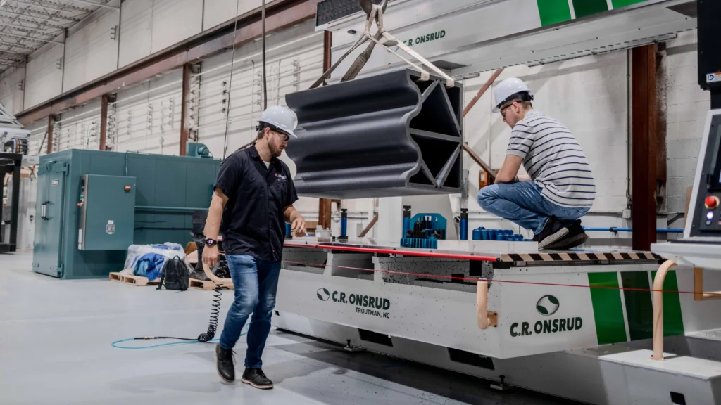
[Above: JuggerBot 3D team prepares LFAM Concrete Precast tool for machining]
Concrete formwork shows how additive manufacturing can expand the definition of tooling. Curved or detailed forms are often difficult from wood. Repeatability is not feasible with wood forms as the tools are sacrificial in nature. Machined metal forms, alternatively, can maintain over several cycles, but can be difficulty to financially justify unless the volume is high. A large-format printed form can introduce complex geometries.
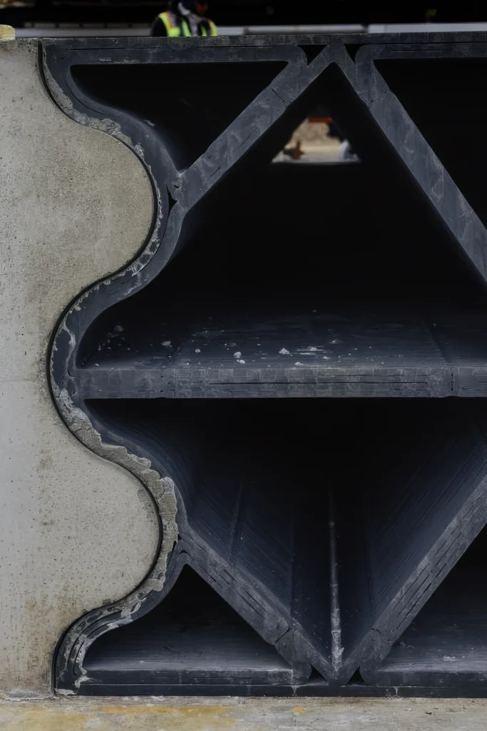
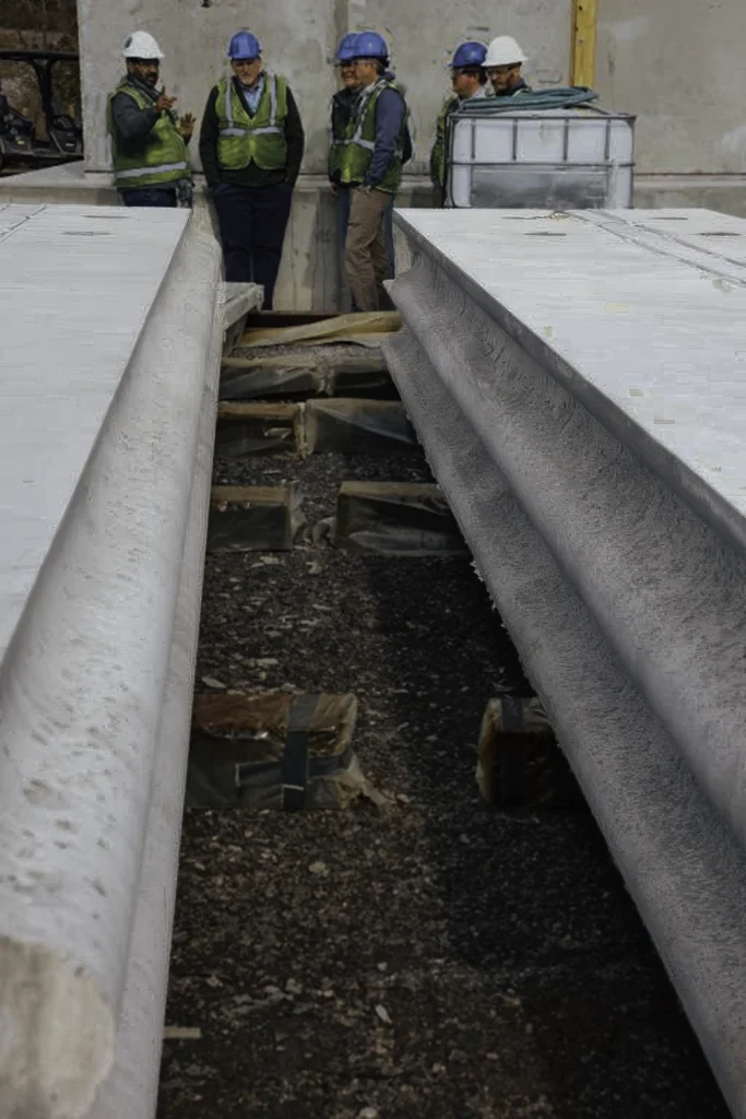
[Left: Concrete Precast Tool curing before release. Right: Finished Precast tool used for Hermes Modern Nuclear Energy Source.]
The approach is especially useful when a form must be reused but does not warrant permanent metal tooling. Printed forms can also support one-off architectural features or precast components whose geometry would make conventional fabrication labor intensive. The form still has to tolerate the weight and pressure of the pour, release the finished component, and maintain its shape across the required number of cycles.
Design Considerations for LFAM Tooling
A conventional tool cannot directly be converted into a printable file and expected to perform the same way. Designing for Large Format Additive Manufacturing is an art itself. Bead placement, layer direction, internal structure, and the machining plan all influence the finished asset. Design for LFAM begins with the final operating requirement and works backward through finishing and printing.
Build Orientation and Tool Surface Optimization
Build orientation determines how layers meet the tool surface and how the printed structure carries load. It also affects print time, support requirements, the location of starts and stops, and access for machining. LFAM tooling is commonly printed near net shape rather than to its final surface. The digital model should include a deliberate machining allowance around critical areas. This additional material, sometimes described as a machining skin, gives the cutting tool enough stock to reach the specified geometry without breaking through the printed shell or exposing the internal fill pattern.
The required allowance depends on expected print variation, tool size, polymer behavior, fixturing, and the machining process. Applying the same offset everywhere can add unnecessary print time and material. A better approach is to identify the surfaces that will be machined, establish how the tool will be located, and add stock according to the needs of those features.
Reinforcement and Infill Strategy
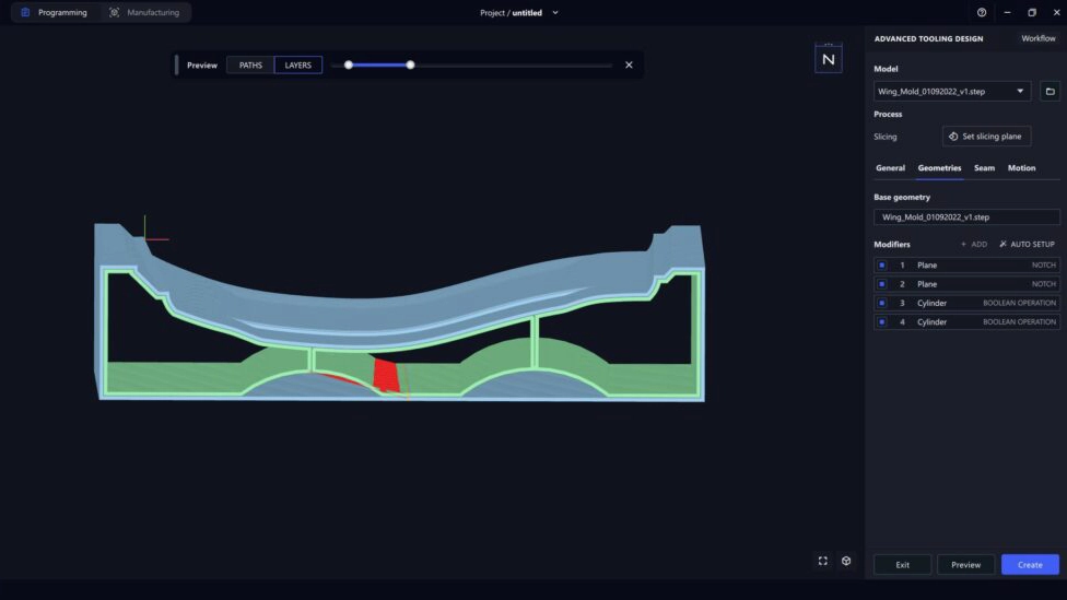
[Above: AdaOne Advanced Tooling Designer]
Printed polymer does not have to carry every load by itself. Infills may control overall stiffness, while wear surfaces can be attached where tools or parts make repeated contact. Designing these interfaces into the model is usually more reliable than treating them as improvised modifications after the print is complete.
Toolpath generation software, such as Adaxis’ AdaOne, can generate infill strategies based on the given tool geometry and where stress on the part may occur.
Material and Thermal Conditions
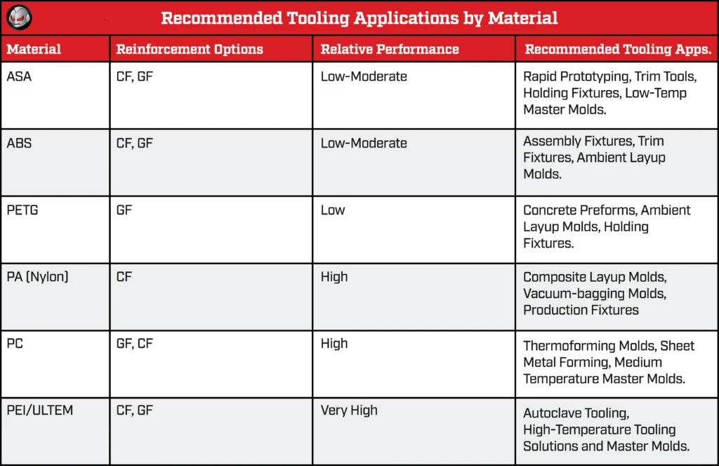
Material selection begins with the tooling process, not the printer. The highest temperature listed for a polymer is not enough to determine whether it will hold a mold surface through a full cycle. The tool may also experience vacuum, pressure, chemical exposure, mechanical loading, or repeated heating and cooling.
Coefficient of thermal expansion is particularly important for large tools. A small dimensional change per unit becomes more consequential and the mold grows. Fiber reinforcement (glass/carbon) can reduce thermal expansion and improve stiffness, but the behavior of the printed structure remains directional because beads and layers are deposited along specific paths. Tool geometry, fiber orientation, and process history all influence the result.
Hybrid Tooling (or Convergent Manufacturing)
The most capable printed tooling programs combine additive manufacturing with established finishing and inspection methods. LFAM produces the near-net-shape structure. CNC machining establishes critical surfaces and interfaces. Metrology compares the finished tool with its digital definition before it enters service. This workflow can begin before the machine starts. Process simulation and toolpath review help determine how geometry will be deposited, where heat may accumulate, and which areas need support or additional material. After printing, annealing or the tool may be used to stabilize the structure. The tool is then fixtured and machined according to the spec provided.
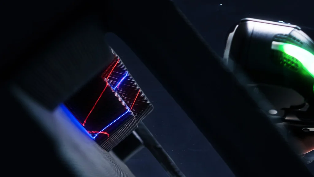
Inspection closes the loop. Scanning or probing can reveal whether the finished surface meets tolerance and whether the tool changed during conditioning or machining. That information can guide a repair, an adjustment to the toolpath, or the next version of the design. In this sense, the digital workflow remains active after the print is complete.
Where 3D Printed Tooling fits in Production
LFAM is most compelling when tool size, geometry, schedule, or expected volume makes conventional fabrication inefficient. It can support early development without limiting the manufacturer to disposable prototypes. It can also serve bridge production, replacement tooling, and qualified end-use applications when the material and workflow meet the operating requirements.
For manufacturers evaluating the approach, the most useful starting point is a specific tool and a clear set of requirements. Tool dimensions, operating temperature, applied pressure, surface tolerance, and expected cycles provide the basis for deciding whether to print, how to design the structure, and what validation is required before production.