
EOAT Case Study
3D Printing Delivers End-of-arm Tooling at an 80% Savings | JuggerBot 3D
Introduction
Just as we humans depend on our fingers to perform everyday tasks, robots depend on end-of-arm tooling to perform any-and-all tasks for which they’re deployed. End-of-arm tooling covers a range of devices that are fixed to the end of a robotic arm, and may be used to manipulate workpieces in a production line, handle tools and equipment, or remove scrap.
Pre-engineered vs Custom End-of-arm Tooling
Pre-engineered end-of-arm tooling is mass produced and can easily be ordered and accessed in a short period of time; they are designed to fit a number of products and may not always be a good fit for manufacturers’ specific needs. Customized end-of-arm tooling, on the other hand, can be designed for a specific purpose and may give manufacturers better functionality during production. However, custom end-of-arm tooling has always been plagued by the cost of low-volume production and spare part management, until now. The rapidly increasing use of additive manufacturing is enabling an era of faster customization and more complex end-of-arm tooling.
As a result, additive manufacturing allows users to produce better functioning end-of-arm tooling for less cost, and at the same time improve the readiness of spare parts to mitigate production downtime.
This paper documents the process and opportunities associated with the use of additive manufacturing to produce custom end-of-arm tooling, with a specific focus from the perspective of the additive manufacturing operator. The material, equipment, and processing are described in detail, and a comparison against CNC-machined end-of-arm tooling is provided.
Challenges
- Verifying wall and feature thickness to ensure strength
- Including the correct assembly tolerances into the design of the rigid arm and flexible attachment
- Infill detail necessary to achieve desired dexterity of the flexible component
- Maintaining conformal cooling of printed parts
Opportunities
- Producing custom end-of-arm tooling, on-demand and directly from CAD
- Reduction of load on robots
- Demonstrated cost reduction for tooling production
- Establishing spare part readiness for manufacturing equipment
Integrating Additive Manufacturing for End-of-arm Tooling
Understanding Customer Requirements
BDI Additive, a division of BDI, was called upon by a longtime FANUC Authorized Systems Integrator to supply end-of-arm tooling (EOAT) designed to handle workpieces on their line. EOAT could not produce scratches and other unwanted marks on the workpieces being handled, and needed to conform to contoured shapes so that uniform pressure could be exerted on the product. The robotic arm is used for a variety of projects, and EOAT changeover is required for every workpiece in each specific job.
It didn’t take long to conclude that additive manufacturing could be used to reduce cost and change-induced downtime.
Establishing EOAT Requirements
It was determined that the best design would be comprised of a robust, rigid backbone to ensure strength and a flexible interfacing feature.
- The two-part EOAT consisted of a rigid backbone for strength…
- … and a flexible component that would conform to the workpiece.
Using Arnitel® ID 2045 and Novamid® ID 1030 CF10
Arnitel® ID2045, a product of DSM Additive Manufacturing, is a flexible thermoplastic copolyester (TPC) with good UV- and superior chemical-resistance compared to other flexible polymers. It is made with 50% bio-based feedstock and prints twice as fast as other TPCs. Final prints benefit from excellent inter-layer adhesion due to its slower crystallization behavior. Arnitel® ID2045 has a Shore D hardness of 34 and was chosen as the build material for the flexible interfacing feature.
Novamid® ID 1030 CF10, also a product of DSM Additive Manufacturing, is a PA6/66 copolymer with a carbon fiber loading of 10% by weight. Compared to other materials, Novamid® ID 1030 CF10 prints durable parts with a high level of dimensional stability and minimal warpage. The integration of carbon fiber and the ability to produce the filament while maintaining fiber integrity results in stronger, stiffer and tougher parts with higher tensile strength and modulus than other carbon fiber filled nylon materials, including those incorporating carbon powder. Novamid® ID 1030 CF10 was therefore chosen as the build material for the rigid backbone.
Design Considerations and Execution
3D CAD software was used to design the new EOAT in two pieces, and a dovetail joint was added to accommodate ease-of-assembly, while a pin was included to the ensure a proper fit between the rigid and flexible pieces. Additive manufacturing made it possible to integrate this “quick-change” design at a low cost.
The 3D CAD design then had to be optimized for additive manufacturing and assembly. BDI Additive reviewed the design to verify that it was taking advantage of additive manufacturing’s strengths, while also avoiding its inherent weaknesses. Simulations were generated in Simplify3D and examined to verify each CAD design revision for the following considerations: (1) width of thin wall features, (2) size of small details, and (3) overhanging features. The considerations are not listed in any specific order and often occur in parallel.
Thin wall features in the design of a part will ultimately drive the thickness of the perimeter, also known as the outline or shell, having a direct correlation to its structural integrity. Walls that will be supporting a load or interacting in an assembly must be robust to avoid failure. A design with thicker walls will allow for thicker perimeters when printing, which allows for higher load-bearing capabilities. Structural integrity is also critical for walls during assembly or integration to ensure that interfacing features withstand forces during the process and fit correctly in the intended location. Typically, three passes of an extruder is sufficient to reinforce a wall. In this project, all designs were configured for a minimum wall thickness of 2.00mm.
Selecting Nozzle Size and Creating Support Structures
Small details must be examined to verify printer setup. If smaller features are critical, a smaller nozzle may be required for printing. By reducing nozzle size, however, operators should expect print time to be extended, and so the option of using a smaller nozzle versus enlarging or eliminating the feature needs to be considered. For the EOAT designs, no small details were limiting factors. Nozzle size was consequently determined to minimize print time with respect to thin wall constraints, as is described in the next section.
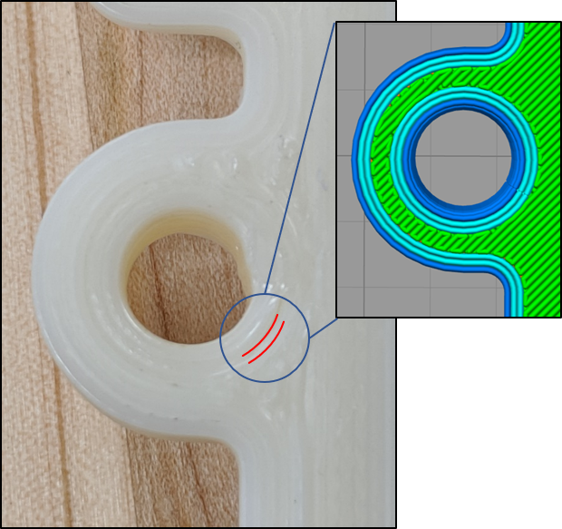
All overhanging features were analyzed to determine the necessity of (1) support material, (2) accessibility of removing the support material, and (3) ideal orientation of printing to minimize support material. However, orientation was dictated by EOAT function in this case, which is explained in the following section. Therefore, overhanging features were adjusted accordingly to minimize and make easy removal of support material.
Optimizing the Additive Manufacturing Process
All printing took place at BDI Additive using JuggerBot 3D’s ‘ME12c’. Designed to process performance thermoplastics, the ME12c contains a built-in dehumidifier capable of reaching temperatures up to 80°C for drying materials prior to printing. The printer is equipped with dual extruders capable of reaching 500°C, each driven through JuggerBot 3D’s patented “Interdependent Drive System”, which leverages both push and pull forces to drive filament of varying properties through the extrusion process. The ME12c also features a heated build plate and chamber capable of reaching 150°C and 80°C, respectively. The printer is controlled through a touch-screen monitor, which is mounted on the front of the machine, and utilizes Simplify 3D software to control the machine and perform slicing operations.
Orientation of the Printed Part
Once the designs were imported to the slicing software (Simplify 3D), print orientation of the part was manipulated and analyzed. Considerations for orientation included: (1) maximum surface area for bed adhesion, (2) amount of support material needed, (4) isotropic strength in accordance with assembly requirements, and (4) maximum nozzle diameter to accomplish all features. Ultimately, the orientation of a print is optimized when the operator has achieved balance among these considerations while satisfying the demands of the application.
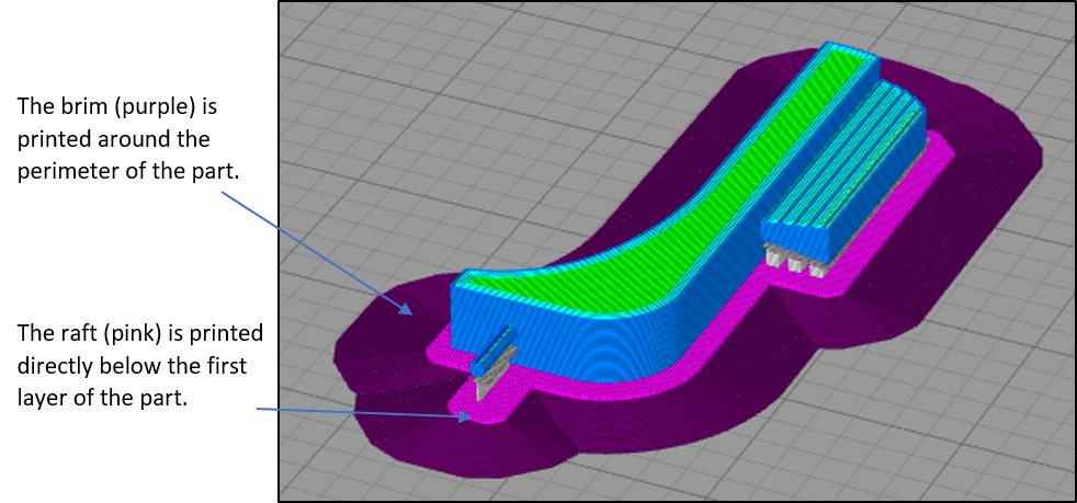
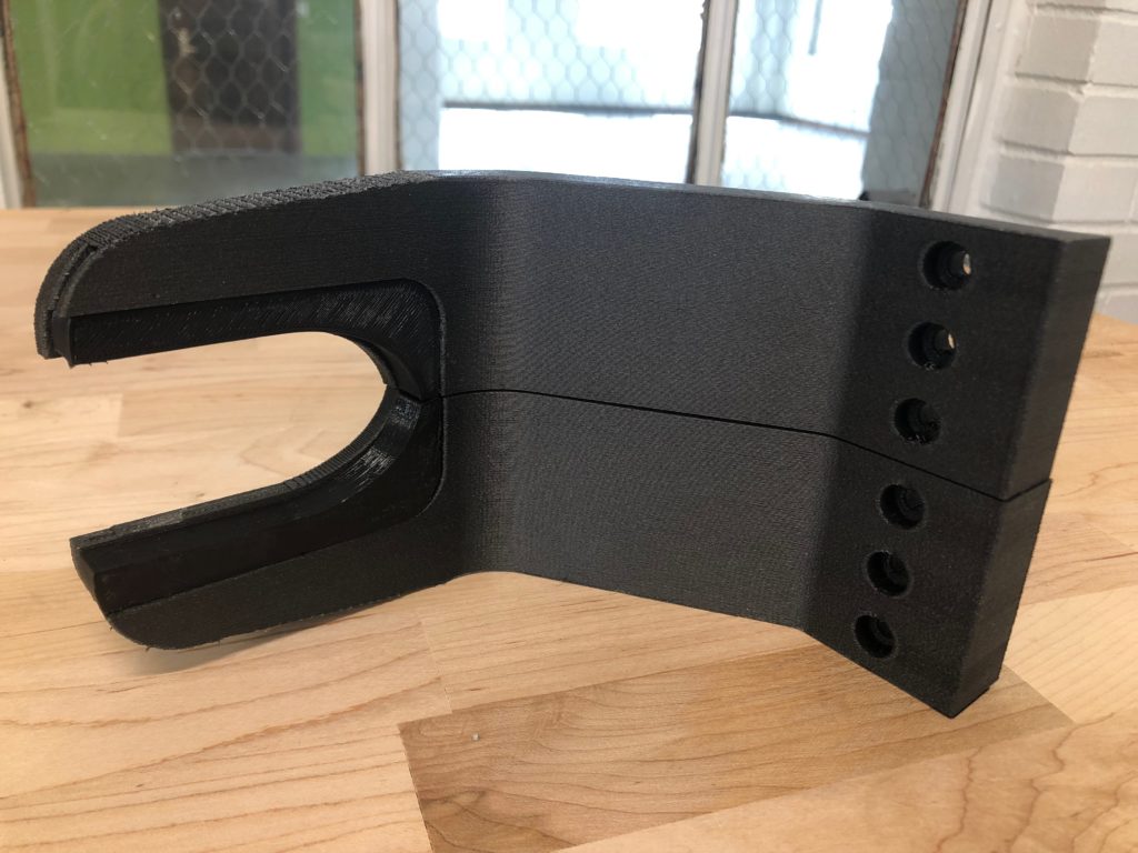
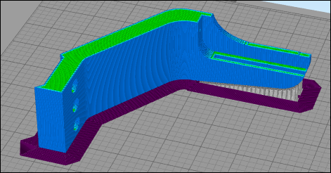
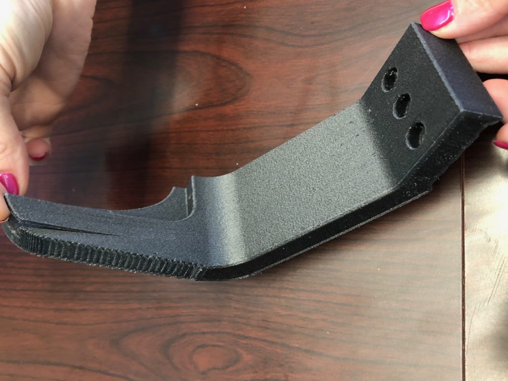
For this project, the prints were oriented so the EOAT was strongest in the direction of load on the arm, as shown in the picture below. Due to the anisotropic strength of 3D-printed parts in the z-direction, the EOAT was oriented to take advantage of the X-Y plane. If the orientation that best suits the strength does not have sufficient surface area, a brim or raft can be added to improve bed adhesion and reduce the risk of warping. A 25-outline brim was added for the printing of these pieces. Support for overhanging features was added to the angle of the rigid arm and the mail dovetail. Support is not typically necessary for bolt holes, depending on their diameter. If support material is needed, it can be drilled out for quicker processing.
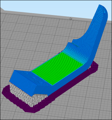
Comparison Against Suboptimal Orientation
An example of suboptimal orientation is shown for reference below. Although this orientation does take advantage of the greatest surface area, it will not produce a fully functional part. The area of the arm that will exert pressure on a product is extending in the z-axis direction, where the tensile strength is less than if that portion of the arm was extending in the x-y plane. This orientation also utilizes 3% more support material than the chosen orientation and would require more time post-processing with a higher possibility of damaging the part when removed.
Setting the Process Parameters
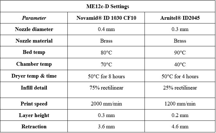
Identifying the optimal printing parameters started with material profiles developed by JuggerBot 3D for Arnitel® ID2045 and Novamid® ID 1030 CF10. A test specimen was printed while the quality of extrusion and adhesion to the bed was observed. During and after this process was complete, imperfections in the test specimen, over/under extrusion, and nozzle height adjustments were identified. Parameters were refined accordingly and a sample part was printed again for additional observation. Once a desirable sample was printed, the parameters were recorded and production began. Refer to Table 1 for the parameters used to print the EOAT.
Completing the Build
Both materials were dried according to manufacturer’s instruction and then the ME12c was prepared for operation. Refer to Table 1 for material preparation steps. The bed was preheated first, followed by the chamber and then the nozzle. It is pertinent to allow for adequate preheat time so that sufficient temperatures are consistent throughout the printer during the build.
The print bed was leveled using an application created by JuggerBot 3D. This application was also used to determine the nozzle offset from the bed. It is important to note that the preheating process needed to be completed prior to running the program, so that thermal expansion could be accounted for within the printer.
The print bed was then wiped with alcohol to ensure a clean surface for optimal bed adhesion. Warping was combated by supplementing the build plate with a thin layer of Magigoo adhesive.
Fit, Form, Function Testing
After the first build was complete, taking approximately 8 hours per rigid arm and 45 minutes per flexible attachment, the components were assembled for fit analysis. The dovetail joint on the rigid arm cracked after the assembly was forced together. The design tolerances were adjusted to reduce the width of the dovetail so the assembly would fit together appropriately, and the EOAT was reprinted and again assessed for quality.
Conclusion
The finished EOAT was then shipped to the customer for installation. Upon initial evaluation, the printed parts appear to meet standards and will be tested in the near future.
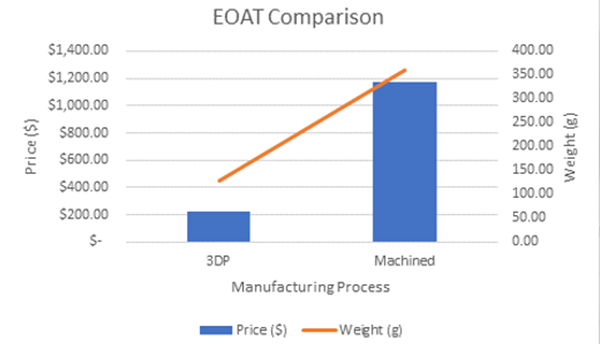
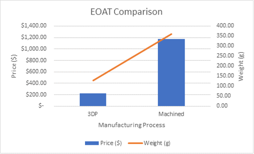
Although limited data is available regarding the performance, data has been collected from a costing standpoint. A quote was received from a third-party service provider and the 3D printed EOAT resulted in approximately 80% cost savings compared to the same EOAT machined from aluminum. Lead time was also decreased by nearly 50%.
The impact of additive manufacturing and EOAT has not been fully explored. Investigation into other materials and types of EOAT should be performed to exploit similar benefits. The use of additive manufacturing to produce adaptive EOAT with other flexible materials, and integrating electronics into the process to produce smart EOAT, is currently being researched by JuggerBot 3D. Additionally, the impact of digital distribution on supply chain management has been evaluated for further integration into BDI Additive’s business.