
BLOG
Webinar: Fused Filament Fabrication vs Fused Granulate Fabrication
Originally aired on April 28th, 2020 by DSM Additive Manufacturing and JuggerBot 3D.
Searching for something specific? Jump directly to a section using the links below:
- Fundamentals of FFF and FGF
- Technical Learnings
- Critical Processing Variables
- Material Testing
- Proprietary vs Open Material Platforms
- The Future of FFF and FGF
- Development Programs
- Question and Answer
Introduction
[Kathleen Meyer speaking]
Hi everyone! I’m Kathleen Meyer, Marketing Specialist for DSM Additive Manufacturing. Welcome to our webinar on filament and pellet printing. Thank you for registering and joining! I’d like to quickly introduce you our three presenters.
Zac DiVencenzo and Dan Fernback are co-founders of JuggerBot 3D, which specializes in building industrial-grade 3D printers. Zac serves as President of JuggerBot 3D and has over 7 years of experience designing, building and operating industrial-grade 3D printers, with a focus on performance thermoplastics. Dan is the Vice President of JuggerBot 3D and has over 7 years of experience integrating additive manufacturing into tooling and production applications.
Our third presenter is Greg Costantino, Application Development Specialist at DSM Additive Manufacturing. DSM draws on years of experience in 3D printing technologies, performance materials and application expertise to unlock the full potential of additive manufacturing, with focus on both sustainable, high-performance materials and processes. Greg is responsible for leading application development programs for DSM.
A reminder that we will have a Q&A session at the end of the presentation, so please submit your questions and we’ll follow up at the end of the webinar.
With that, I’d like to hand it over now to Zac.
[Zac DiVencenzo speaking]
In this webinar, we’re going to cover and explain three segments that we believe are important when considering 3D printing as your manufacturing process.
First, the Fundamentals of FFF and FGF technology.
Here, we’ll capture some key differentiators and similarities. We’ll then dive into some of the engineering grade materials available for these technologies and inform you on what to consider when aligning materials to your applications.
Second, we’ll dive into Technical Learnings.
This should help everyone understand the critical variables, and provide some guidance on what technology to use. We’ll then review material testing, demonstrating how 3D printing stacks up within FFF and FGF and other manufacturing processes like injection molding.
Last, we’ll give a general overview of Open and Proprietary Material Platforms, explaining some limitations and shortcomings, and then take a look into the Future for the Technologies reviewed.
So, let’s get started!
Fundamentals of FFF and FGF
Material extrusion 3D printing is a method of extruding thermoplastics and, over the past couple decades, it’s been creating new possibilities for part designs. It enabled engineers to think outside of traditional manufacturing like machining, casting, and molding and allowed the freedom to create more complex geometries. In a way, 3D printing has been both a disruptive and an incremental innovation; disruptive in the fact that it’s different from how we think about manufacturing today, but also incremental, as we’re utilizing existing methods for new technology.
Within material extrusion, two promising methods have emerged and are being used today for rapid prototyping, tooling, and final part production.
Fused Filament Fabrication
Fused Filament Fabrication is the process of extruding a thin strand, or filament, of thermoplastic material through a liquefier and depositing it layer upon layer in a pre-determined tool path.
The mechanics of the extrusion system are quite simple, similar to what you would see in traditional arc welding. The strand of filament is being pushed or pulled into a set of direct drive rollers in a pinch system format. This feeds the material into a heating zone and then through a brass or steel nozzle. Nozzles size can be customizable and changed for each part.
Fused Granulate Fabrication
Fused Granulate Fabrication (FGF aka Pellet Printing), is a similar process to FFF, but instead of using a strand of thermoplastic, it utilizes granules of the material, meaning pellets.
The mechanics are still simple, but now incorporates a robust barrel and screw extrusion system [similar to] traditional plastic extrusion and injection molding. Pellets are gravity fed into a feed section, where it makes contact with a screw. A servo motor drives the screw, which conveys the pellets through a heated barrel. The barrel has multiple heating sections, allowing the material to progressively heat up and melt. Similar to FFF, the material is then forced through brass or steel nozzles. The nozzles are also customizable to fit the part and application.
Now let’s recap and compare FFF to FGF.
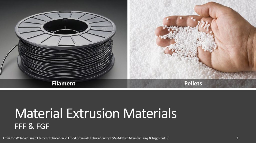
Feedstock
With the feedstock, FFF uses filament – a strand of thermoplastic material, and FGF uses granules or pellets. Please note that the filament material for FFF starts out as pellets and that FGF skips the additional manufacturing process. Theoretically, material has went through one less heating cycle, and one could claim that in pellet form, the material will process easier and could very well perform better during and after the printing process. Also, the pellets will be cheaper compared to the filament simply based on one less manufacturing process.
Material Base
As Greg will capture later on in the webinar, the availability of different thermoplastics ranges within FFF and FGF. There is a wide range of materials to choose from within the FFF process, but even a broader range in the FGF due to the way its manufactured and supplied.
Throughput
When we talk about throughput, we’re talking about the rate of flow or the amount of material extruded in a particular time frame. For FFF and FGF, we use lbs. (pounds) per hour. Thinking about how the FFF processes the strands of thermoplastic, the limiting factor when it comes to throughput is the ability to heat and melt the material. Even though the cross section of the filament is small, the heating zone is short and can only transfer heat so fast.
For FGF, the limiting factor is the size of the extruder and the screw design. To give everyone a sense of throughput for each process, FFF could range from 0.005 lbs./hr. to 0.25 lbs./hr., and for FGF, it could range from 0.50 lbs./hr. – 20 lbs./hr. The diameter of the nozzle and type of thermoplastic directly effects the throughput. Later on in the webinar we’ll capture other variables in the printing process that can also affect the throughput.
Resolution
Resolution refers to the layer height and road width of the extruded material. With smaller nozzles and using the thin strands of filament, you can achieve a higher level of resolution with FFF printing. Layer heights can range from 0.15mm to 0.4mm. and the width can range from 0.3mm to 1.00 mm. FGF has a lower resolution, with a layer range of 1mm to 5mm, and a width range of 2mm to 10mm.
Print Dimensions
Parts produced by FFF tend to be small. That’s not to say that you can’t print a three foot by three foot part with FFF, but due to the resolution and throughput, the time to produce a large part may not be economical or efficient. The build could be 200 times longer than on an FGF machine and with a higher risk of failure on longer print cycles. With the resolution so low, FGF lends itself to larger prints. You can print a large part in just a couple hours.
Print Complexity
Parts printed using FGF will have less features and will be considered as low complexity, based on the low resolution and wider extrusion paths. With FFF, you can print more detailed parts, with complicated features, again due to the smaller nozzles and bead width.
Tool Path
Tool path refers to the programmed path through space that the extruder with follow to print the desired part geometry. With FFF since the part complexity and resolution is high, the tool path is also complex and has a lot of movements. The excessive movements ultimately reduce the throughput. For FGF, the tool path movement is simpler, but more time and focus is needed in the design phase before printing to avoid the tool path crossing over itself. Technically, this should be considered for both processes, but the results for FGF is a magnitude greater. If the extruder head lays down material in a particular path, and the material cools and hardens, you would want to avoid the print head cross over the harden material. This will cause serious damage to the system.
Temperatures
The goal for FFF is to get more heat into the material so that you can print faster and so the material doesn’t crystallize too quickly. The biggest factor in FFF is preventing the thermoplastic material to crystalize before the subsequent layers are printed. You have to remember: material extrusion 3D printing is anisotropic – the X and Y direction is stronger than the Z direction when it comes to tensile stress. This is a laminate process and you care about the interlaminar bonding. For the material to best stick to itself, the material still has to be in an equivalent state.
For FGF, the problem is the opposite. We want to get the heat out of the material. Due to the screw driven process, friction occurs and shear heating is the result. The heat put into the material from the screw will likely be greater than the temperature of the barrel. This is called melt temp. With the throughput being so high in FGF, if the temperature of the material is to great, initial printed layers could be too weak hold up the subsequent layers. Sagging will occur in the printed layers and could cause a poor quality, or worse, a failed print.
There is a lot to consider when thinking about FFF and FGF technology and knowing about the material available is the first step. Here’s Greg to explain more.
DSM Additive Manufacturing Solids Portfolio Base
[Greg Costantino speaking]
DSM Additive Manufacturing is striving to push 3D printing to its full potential by drawing on decades of experience in additive manufacturing technologies, deep application development expertise and performance materials to help manufacturers change the way they design and manufacture products.
The DSM AM group is leveraging the portfolio of our sister division, DSM Engineering Materials, to create the solids products which currently consist of filaments, pellets and powders. The base resins being utilized are highlighted inside the pyramid. The core of the products are based on nylon and polyester chemistries with an emphasis on higher performance polymers.
As noted in the introduction, we are emphasizing the creation of sustainable products based on recycled or bio-based content.
Utilizing this portfolio of engineering thermoplastics gives the ability to meet more stringent application requirements vs the DSM Somos® liquid photopolymers since the thermoplastic materials have higher mechanical and thermal properties, as well as a greater resistance to chemicals. This makes them well suited for more stringent applications in industrial, transportation and electronics markets.
DSM Material Solutions – Solids
Our filaments portfolio currently consists of seven products, four nylon-based materials and three polyester-based.
The nylon-based materials are highlighted by two higher performance products. The first is a carbon fiber filled PA666, which offers 3.5x the stiffness and 2.5x the strength of our standard PA666. The second product is a flame retardant PA666 which has a UL Blue Card listing.
The polyester based materials are highlighted by a PET polyester which offers a higher level of dimensional stability and two co-polyester based materials. The highest temperature performing product is Arnitel® ID2060 HT which has been tested at elevated temperatures of 190C for 500 hours and 175C for 1000 hours which make it suitable for the most stringent under-the-hood applications.
The pellet portfolio currently consists of one commercial product which is a highly filled PET polyester. The current plan is to launch at least three new pellet grades this year.
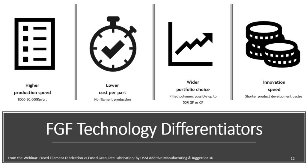
FGF Technology Differentiators
When comparing the two print processes, there are some key differentiators for FGF we would like to emphasize. The first is higher production speeds. Based on higher throughput, we see the ability to print up to 200x faster than traditional printing. Material choices are also much broader since the type and quantity of fillers that can be used across multiple resins systems are greatly expanded since the creation of filament is bypassed. As a result, total part cost is greatly reduced which makes this printing technology more competitive with traditional manufacturing processes. Lastly, the amount of time spent in the development cycle can be decreased when utilizing faster print times resulting in faster iterations of part designs.
We will now discuss some of our technical learnings on the two technologies. The focus of this section will be on material handling, selecting the appropriate material for the application, print process variables and material properties.
Technical Learnings
[Zac DiVencenzo speaking]
After hearing about the fundamentals of both material extrusion methods and understanding the materials available, we would like to review some technical learnings that can shed some additional light on the technology and how to use it.
Material Handling
The filament used in FFF is produced either in 1.75mm or 2.85mm strand diameter and wound onto a spool. These spools are stored and loaded into a 3D printer and unwinds as the material is extruded.
For FGF, before any material is extruded, the plastic raw material is first contained and dried in an industrial drying hopper, typically located outside of the machine. The material is called upon from sensors within the machine and is conveyed through corrugated tubing to a smaller secondary hopper.
With both types of additive manufacturing processes, consideration to proper material storage and pre-processing procedures can help to ensure effective results. Regardless if the material is in pellet or filament strand form, there is an importance of drying the polymer and keeping it dried throughout the duration of printing.
The Importance of Drying
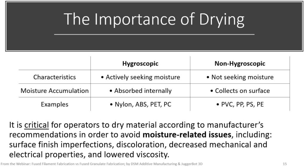
Polymers can be either hygroscopic or non-hygroscopic, each type having a set of processing characteristics that have a certain affinity to gather moisture.
Materials like Nylon, ABS, PET and Polycarbonate are hygroscopic, and are actively seeking moisture to absorb internally. PVC, Polypropylene, Polystyrene and Polyethylene are non-hygroscopic. These materials do not absorb moisture internally but can collect moisture on the surface. Moisture in polymers plays a serious role in how the material will extrude and will perform once extruded. Moisture can affect surface finish and cause discoloration, lower the mechanical properties – impacting strength and elongation to break, effect electrical properties, and even lower the viscosity.
For some materials, it’s easy to notice moisture as you will see excessive drooling from the barrel, bubbles on the surface of the extruded material, and even off gassing of any water vapor trapped inside. For other materials, it may not be directly noticeable and will leave you to believe everything is okay. It won’t be until after you begin printing that you can see a direct effect. Delamination of printed layers will be one of the detrimental issues you will experience.
For filament, manufacturers will supply vacuum sealed packages to avoid moisture, but it’s still up to the operator to make sure the material is dried before processing. The operator will need to pay attention to the spool and what type of material it was made out of. Each polymer will have a particular drying procedure, and you should make sure that the material used to make the spool can perform at the temperature required to dry the filament.
For pellets, the manufacturer will supply the user with various sizes of vacuum sealed bags and, again – like the filament material – it is up to the operator to dry the material before printing.
What Technology to Use
So, what technology should you use? Here are some things to consider if you currently own the technology or you’re currently looking to bring it in-house.
The first thing to determine before selecting a process is what material to use. If the part is for prototyping, then match a material for either fit, form, or function, or all. If the part is for tooling or for final part production, then you will utilize a material best used for the application or match the material that is already currently used in the industry. The material of choice can be the first step of determining the right technology. As it was explained earlier in the webinar, there is a range of thermoplastic material in filament form, but not everything is readily available.
Once material is selected, you may be in a situation where FGF is the only available technology, but it doesn’t suit the part design. You may need to re-determine your material requirements and see if an available filament can work. If not, material extrusion technology in general may not be best for this part design in question.
If you’re in the situation that both technologies can use the material you selected, you then move on to the part at hand, and review it with some design considerations.
Process Considerations: FFF
For FFF, you will look to see if the part is:
- Small to medium
- Thin walls
- Small features
- Small holes
Again, with the smaller nozzle diameter, smaller bead width and smaller layer height, FFF technology will allow you to print thin-walled, highly complex parts. But as you grow in size, the time to print may be of concern and may lead you down the path of FGF.
Process Considerations: FGF
- For FGF, you will look to see if the part is:
- Medium to large
- Thick walls
- Low complexity
- No overhangs (doesn’t require support material)
Now keep in mind, parts produced from FGF technology can be put onto traditional subtractive equipment and be milled to final part design. This is called near net shape printing. You will enlarge your part design, print it fast, then machine it down to your final dimension. With FGF technology starting with a cheaper material option, and the speed to print is upwards of 200X faster than FFF, having an additional machining cost to your production is very minimal. This can also help you achieve higher production tolerances.
Critical Processing Variables
Before printing an actual part, there are a couple critical variables that need be established, some that we’ve already talked about in this webinar. Nozzle Diameter, Bead Width, Layer Height, Temperatures and Speed. These variables will dictate flow rate and your throughput, strength of the part, and even the quality. Most slicing software packages will let you review the tool path in a simulation format after you have determined these variables. The operator will look for any problems throughout each layer, making sure the features can be produced and ensure efficient printing.
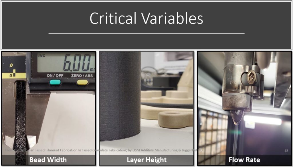
Bead Width & Layer Height
Accurate bead width and layer height is what’s most important for dimensional accuracy. The machines we develop incorporate robust industrial gantry systems that demonstrate excellent precision and repeatability. What will really dictate the part dimension and the tolerance is how accurate the operate can dial in the critical variables already listed.
With open source machines and materials, one of the most common problems with achieving tight tolerances is not matching the proper bead width and layer height to the wall thickness and height of the part.
It’s important to make sure the bead width is smaller than the minimum wall thickness on your part, and it will be considered optimized if you can make sure the bead width is an even divisible number of your wall thickness. If you attempt to print with a 1mm nozzle, and your minimum wall thickness is .4mm, you run the risk of the tool path missing this section completely as the machine is printing. The software available today is not intelligent enough to alert the operator of this mistake. The operator should be able to catch this during simulation, but you may end up overlooking it and getting a firsthand experience during the printing operation. You can attempt to print beads smaller than your nozzle, but what you are actually doing is under extruding, and it will not be consistent enough to hold any particular tolerances.
This goes the same for selecting the printed layer height. The layer height or “resolution” is a fixed variable. The printer will move in two dimensions, left to right and front to back, then index one layer at a time up or down. The layer height will first be derived from nozzle dimeter selected. A good start would be using 60 to 80% of the diameter. If you have a 1mm nozzle, start somewhere between .60mm and .8mm. Then you’ll try and make sure the layer height is an even divisible number of the total height of the part.
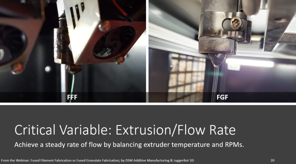
Extrusion/Flow Rate
After selecting a nozzle diameter, knowing what bead width and layer height you want, establishing a flow rate will be next to ensure accurate part dimensions. The trick is to achieve a steady consistent rate of material flow, where material is at a temperature that melts and bonds well to the previous layers, but also be rigid enough to hold itself up throughout the duration of print. The rpms of the screw or rollers need to be matched with the speed of the gantry to achieve the desired bead width. Simple right?
The procedures for FFF and FGF are similar as they are both processes of extruding thermoplastics. Other than the mechanics, the only real difference is the scaling of it.
The manufacturers of the filament and pellet material can help you by providing a range of temperatures to start with. It will be virtually impossible for them to provide an exact temperature to use since each 3D printer manufacturer uses different equipment and temperature sensors that could provide different readings. To avoid degrading material, it is always smart to start at the lower end of the range. While testing temperatures, you’ll be looking for a constant flow, showing a consistent diameter. If there is any interruption, you will want to take a look at the feed mechanism, and if everything looks okay, then you can increase temperature to reduce high pressures inside the extruders. If the material looks too thin after extruding, or if the material drools out of the nozzle, you may be too hot and want to cool it down.
After feeling comfortable with the extrusion flow, selecting gantry speeds will finally determine the accuracy of your bead width. If you select a speed that’s too high for the rpms of the extruder, the bead will thin out and be smaller than you planned. This is called under extrusion. Then the opposite, if the speed of the gantry is too low for the extruder, then the bead will enlarge. This is called over extrusion.
Lastly, we have to remember that carbonizing, or degrading of the thermoplastic material may occur. You have to careful to not improperly heat the material or let the material sit at too high of a temperature for too long of a duration. In FFF, due to the small heating section, you are less likely to degrade the material, and if you do, you only degrade a small portion of it. The outcome would be small as you may need to change out a new nozzle, or even just change out the extruder. Thirty minutes and $200 later, you’re good to go. For FGF, it is very easy to degrade the material. The outcome is much worse and could result in thousands of dollars in repairs and the machine being down for the day.
Finding the balance is key to material extrusion and what truly makes the difference between a good operator and a great one.
Tensile Specimen Preparation – FFF
[Greg Costantino speaking]
Next, we will discuss specimen preparation for filament and pellet printing along with material properties of each technology as compared to injection molding.
Preparation of tensile bars were done by printing them in two orientations. Hexagonal shapes were printed from which test bars were milled from each face of the hexagon. This gives an indication of the interlayer adhesion, or z-axis strength, since the pull direction is perpendicular to the print direction.
On-edge samples were also printed which consists of printing rectangular samples from which test bars were milled. This gives an indication of the strength of the filaments in the print direction since you are pulling along the filament length.
Results: Novamid® ID1030 CF10 Tensile Strength
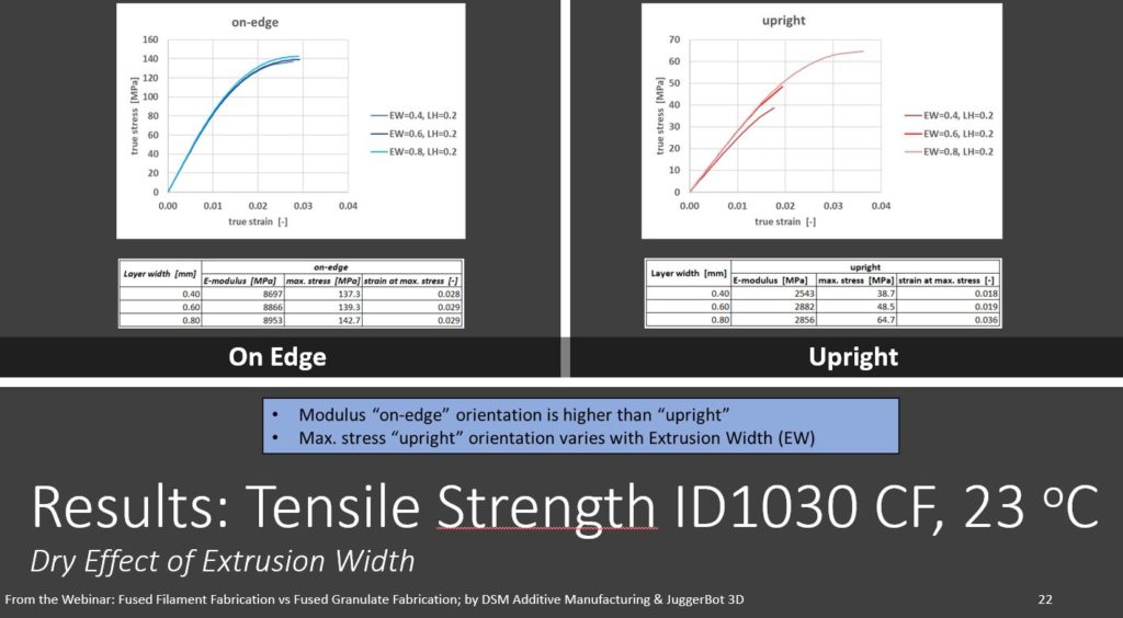
In this slide we show some of our test results at room temperature for Novamid® ID1030 CF filament. Print trials were performed with various bead widths, or extrusion widths, while keeping the layer height constant.
The properties of the on-edge specimens show higher properties than those printed upright, with modulus values being 3-3.5X greater and tensile stress being 2-3.5X higher. A key observation shown in the graphs is that the stress values from the on-edge specimens are very similar even as the extrusion width changes with maximum stress varying only 5.4 MPa and strain remaining virtually unchanged. The stress values from upright specimens show a change as the extrusion width varies with a deviation of 26 MPa and strain values decreasing 50%.
Explaining the Differences, On Edge vs Upright Specimen
Focusing on the graph to the left – at a high level, the differences observed in the on-edge vs upright specimens are explained by two phenomena. The first is that the fiber orientation in the on-edge specimens is much greater since the filament layers are in direct alignment with the pull direction, while upright specimens are being pulled perpendicular to the direction of the filament layers. Any micro-voids present between layers could also provide an area of weakness, especially in the upright specimens since the stress is being directly applied to the area between layers.
Switching now to the graph on the right – as previously noted, there was a change in stress values of the upright specimens as the extrusion width changed. These results are related to the amount of energy involved to fuse the layers together. Wider beads correspond to the presence of a higher level of energy which result in better bonding and thus higher stress values.
Arnitel® ID2045: 3D Printing vs Injection Molding
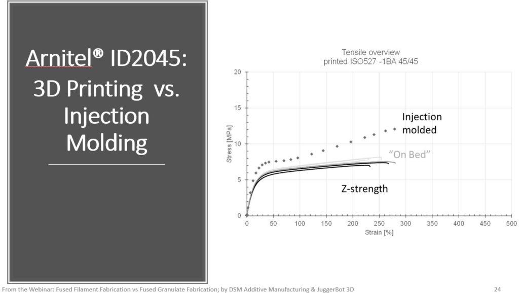
A high level of focus has been placed in trying to generate properties comparable to traditional manufacturing processes. We have two thermoplastic co-polyester products in filament form and work has been done with these grades to show a comparison to injection molded properties. The graph shows results from tensile strength testing of bars printed in four orientations of our standard thermoplastic copolyester filament and a comparison to injection molded bars of a similar grade. We are continuing to do work in this area to improve this correlation of properties to injection molding.
Arnitel® ID2060 HT: Heat Aging
Arnitel® ID2060 HT is designed to have higher thermal performance and mechanical properties have been tested after heat ageing up to 190°C. This graph shows the change in modulus during heat ageing at 175°C for 1000 hours as compared to a similar injection molding grade. A nice correlation of performance is observed across most of the heat age duration.
Tensile Specimen Preparation – FGF
Now discussing some of the work that has been done with pellet printing, tensile specimens were prepared by first printing four sided cubes and then machining tensile specimens using the layout shown in the figure. The layer thickness can vary depending on what the goal of the testing is, and the size of the cube can be altered depending on the number of samples needed.
Arnite® AM8527 (G) – 3D Printing vs Injection Molding
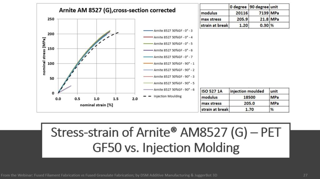
Stress-strain data was generated from bars milled from the x and z axis as shown in the previous slide. The data is corrected for the cross-sectional area. Vastly different results are noted in the stress-strain behavior in these two axes with the results of the bars machined in the print direction showing significantly higher maximum stress values.
When overlaying stress-strain data of a comparable injection molding grade, a very nice correlation is observed. Slightly higher properties are observed with 3D printed bars which is most likely due to better overall alignment of fibers in the printed beads vs the alignment of fibers that is achieved in the injection molded bars.
Technical Learnings Summary
A high-level summary of what was reviewed today is as follows:
The first item is that an understanding of material handling requirements, especially drying, of the respective material you are printing is critical to your success.
Secondly: there are various advantages of FFF and FGF you should consider when selecting which technology to utilize for your application.
Third: after you have determined which technology you will utilize, the most critical print process parameters for optimization to obtain the best appearance and strength of the part you are printing are bead width, layer height and flow rate.
When evaluating mechanical performance of the material you are using, you should be aware of the print direction in respect to the part orientation. When keeping other parameters constant, the extrusion width is noted to have a direct impact on mechanical performance.
Lastly, the performance of 3D printing technologies are often compared to traditional processes such as injection molding. You should consider all the factors in the print technology you are using in comparison to the actual behavior of the part in your application when evaluating performance.
[Dan Fernback speaking]
As Zac and Greg outlined, there are many similarities, but also distinct differences between Fused Filament Fabrication and Fused Granulate Fabrication. With both, there are a number of opportunities and so we’d like to share a little about the future of both technologies, and collaborative programs we’ve established to streamline the development process. But first, we want to touch base on one more important factor to consider in moving forward with 3D printing.
Proprietary Material Platforms vs Open Material Platforms
Something to consider when investigating potential additive manufacturing solutions is whether you’re considering open material platforms or proprietary material platforms.
In short, open material platforms, like JuggerBot 3D, allows users to process materials from third party material suppliers, like DSM Additive Manufacturing. On the other hand, proprietary platforms lock down the materials so users can only buy from a particular vendor.
Before we compare the two different platforms, it’s important to state that holistically, it’s not a ‘good vs bad’ debate, instead it’s more like the comparing Android’s mobile platform with Apple’s iOS platform. Each one has its place and it really boils down to the ultimate user’s preference as to which platform is best for them.
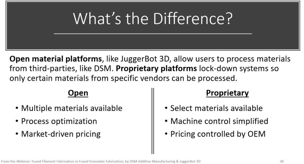
For 3D printing, the high-level differences between open and proprietary platforms boils down to (1) the selection of materials available to operators, (2) the controls operators have over the printing process, and (3) the price to acquire and operate 3D printers.
Proprietary Material Limitations
To touch on that a little more, common 3D printing materials have traditionally included lower cost commodity plastics like ABS, and high cost, high performance plastics like PEI.
And unfortunately, there are shortcomings with these – primarily amorphous materials – especially regarding their wear-ability, their abrasion and chemical resistance, and issues pertaining to environmental stress cracking.While these plastics are a great fit for some applications, new materials being introduced through open platforms are enabling operators to find the best fit for their need. The open material platform enables us as operators to let material be driven by the application, and also ask ourselves if the traditional high-performance materials are worth their high price tag. In some cases, new materials may offer better performance and price, as shown in the table below provided by Curbell Plastics.
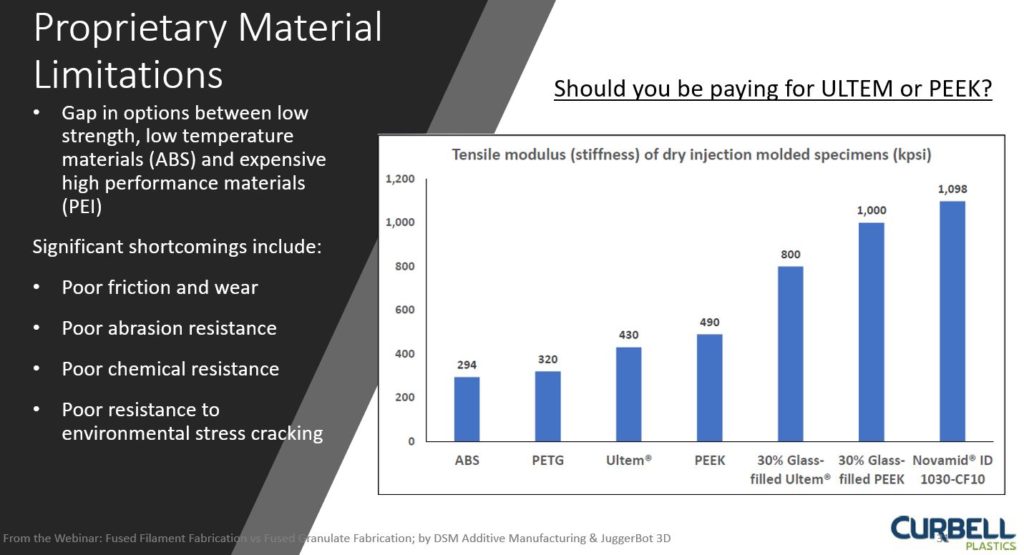
When comparing the mechanical properties of DSM’s Novamid® ID 1030 CF10 against other materials available for 3D printing, it proves to be much stiffer and in many cases is less costly.
Now, if you want to tap into third party materials, you’ll be dealing with different variables given the different vendors – even if the material is the same spec, so next we’re going to talk about process parameters.
Proprietary vs Open Platforms: Process Optimization
Prospective users should be thinking about the amount of control they’d like to have over the printing process.
Some people would prefer to be more hands off, where the operators require less training and the setup is more streamlined, and in that case the proprietary platforms may be a good fit for them.
Others, however, are in a position where controlling the process parameters doesn’t only mean they can use a material that best fits their customer, but also is a means to differentiate themselves and/or improve their profitability! With the ability to control process parameters, a competitive edge could be set by simply being able to configure the printer in a way that’s best for the parts being printed, it could also mean reducing material cost and additional process by customizing the infill patterns and support structures. In these cases, an open material platform is the best tool for the job.
Proprietary vs Open Platforms: Cost
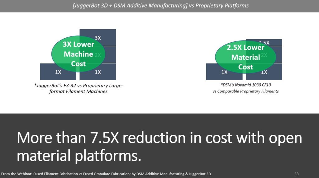
Last, a common result of open material platforms is market pricing, meaning the machines and materials are generally less expensive than their proprietary counterparts.
For example, in evaluating costs for comparable machines and materials offered by JuggerBot 3D and DSM Additive Manufacturing, against an industry leader which offers proprietary platforms, the open material platform is 7.5X less to acquire and operate!
The Future of FFF and FGF
As we continue grow our capabilities by addressing additive manufacturing’s biggest issues:
- Material limitations
- Scalability
- Cost
We know that focusing on real opportunities with end users is absolutely critical in further expanding on applications to produce tooling and even production parts.
Tooling and Production Opportunities in 3D Printing
For the past three years, JuggerBot 3D and DSM have worked together to tackle 3D printing applications, converging know-how and prospective from JuggerBot 3D regarding the machines and process, with expertise from the material side – built from DSM’s decades-long reign as a leading material supplier across the globe.
We’ve worked with 3D printing service bureaus, contract manufacturers, and OEMs alike to first, identify opportunities where 3D printing thrives, and then develop a fully-stacked solution that best fits the application.
DSM Additive Manufacturing & JuggerBot 3D Development Programs
We are committed to continuing these efforts for companies at all stages of development – from new comers to those pushing 3D printing to the forefront of production, and encourage interested parties to contact us by visiting www.juggerbot3d.com/application-development/ , which will direct you to a page on JuggerBot 3D’s site that looks just like this.
As you scroll down the page, you will see a brief description of our the programs being offered for both filament and pellet-extrusion technologies, and can easily get ahold of us by completing the form at the bottom of the page with general information about your company, yourself, and the goals for your program. After submitting the information, we will be in contact right away to continue!
Q&A Session
Can you briefly talk us through the different post-processing options for FFF and FGF?
The first post-processing step may be the removal of the support material from the 3D printed part. If water soluble support material is utilized, the operator will let the part sit in warm water for a several hours and let the material dissolve over time. In times that water soluble material cannot be used, materials like HIPS (high impact polystyrene) is used, as required for the material – the part will sit in a chemical bath to dissolve the supports.
When it comes to achieving an immaculate finish with high dimensional tolerance, light facing or machining of the printed part is an option – though more expensive and time consuming. Other traditional methods to improve surface finish – to make it look like an injection molded part – could be abrasive blasting like sand blasting, matte finishing like tumbling and polishing, buffing and sanding are all great methods to use. Final for finishing is applying coatings or paint.
Does DSM produce filaments or granules for ESD application?
We currently don’t have any commercial products for ESD but we have done some work in that area, as well as with potentially thermally conductive grades. Those are still in the product development stage.
Is printing with supports feasible for FGF?
It’s not desired due to the way the plastic is distributed – high volume with higher temperatures. The beads are massive. With filament printing, you’re working with a thin strand and it’s easier to use a tool or chemical bath to remove the supports. Thinking about FGF parts – the large machine JuggerBot 3D offers has printing space of three feet by four feet by four feet, and typically there is not a chemical bath basin that is offered to remove the supports. It’s also not as easy since the beads are wider, so it’s like using channel locks to remove the support material. It’s best, if you are going to use support material, to finish the final part with a machining process and machine the supports away, or orient the machine to the best of your ability to avoid any overhangs.
What applications have you seen the most success with so far?
For both filament and pellet extrusion technologies, our early wins have been in the tooling space, specifically for patterns and sand casting, as well as molds for thermal forming and being able to produce parts with higher performing thermoplastics on the FGF side – like dies for sheet metal forming. In addition, we’ve done a lot of work with jigs and fixtures, specifically with routing fixtures and masking fixtures, and robotic tooling like end-of-arm tooling.
We’re starting to do a lot more now in production, especially being able to print up to 200x faster on the FGF printer – our P3-44. We’re focused on working with OEMs and Tier 1s in the Aerospace, Automotive, Medical and Energy industries. But focusing where 3D printing thrives – areas where producing parts on demand is a competitive edge, or mass customization can play an active role in development of a business as well as being able to leverage design freedom from AM.
Can you discuss technical limitations for FGF when it comes to nozzle size and wanting to produce highly detailed parts?
The size of the part and material you are trying to print will likely determine what size nozzle can be used. For example, if you have a highly-filled, higher viscosity grade, you can only go so far down in nozzle size. We have seen some cases using small nozzle sizes and still have nice resolution. It depends on the application you’re trying to print, the material you’re using and the surface appearance you’re trying to achieve.
How important is it to have a heated build chamber?
The main importance is controlling the environment in general. Regardless if you’re increasing the ambient temperature, you want consistency within the machine throughout the duration of the process. Interlaminar bonding is crucial – it’s the biggest weakness within pellet extrusion printing – you want to make sure the deposited material bonds well with subsequent layers. Using a controlled and heated chamber allows the operator to prevent the parts from cooling too rapidly, reduce warping which ultimately helps insure the accurate part dimensions. A heated build chamber ensures sufficient bonding and increase or decrease the strength of the printed part in the z direction.
Would FGF work for soft and flexible materials?
This would depend on how you define soft. For example, DSM has two Arnitel filaments. The softer one has a 34 Shore D. We know there are complications if you go too soft – a 70 Shore D or lower – could pose challenges. An advantage of the JuggerBot 3D system is its push-pull system to feed softer filaments in the machine. It can handle what a lot of other systems cannot. Generally, we do see some softer materials used, but you can go too soft. We haven’t had too much experience yet with post-finishing, but again – generally – there’d be challenges depending on what type of support material is being used and how to break it away.
How sensitive is FGF to oozing out of material when jumping to a new start point? Does your equipment utilize special technology to stop flow of material when not printing?
In filament printing, it’s natural to set an open source machine to do a retraction – retract the filament and reduce the pressure so it doesn’t ooze, then over extrude when you start. In pellet printing, you’re not able to retract (turn the screw backwards), so within the slicing software we utilize, there are a few techniques to address this. One – appropriately coast into the start and stops. Essentially reducing RPMs of the screw or turning off the screw 6-10 mm before the end of segment. Then rebuild pressure, you may slow down the gantry to allow pressure to build up to allow a clean start or increase RPMs for a short time.
JuggerBot 3D utilizes Strangepresse pellet extruder equipment and through Oak Ridge National Lab technology we incorporate a system that basically reduce pressure so we can eliminate oozing altogether. Using these techniques are band aids: oozing is typically connected to temperature – it’s important to match the temperature with the extrusion process itself and the filament you’ve selected.
If I want to evaluate and FGF part for my application, how do I request a benchmark? Where can I order prototype parts in DSM materials?
Whether it be for parts or even consultation, the easiest way to communicate is to visit JuggerBot3D’s website. We have a page dedicated to application development (shown on last slide of presentation). Fill out the form and provide some detail on the part and we’ll follow up.
Can any material in pellet form be printed with FGF?
Short answer: we don’t know yet. We suspect that, like other traditional manufacturing methods, some materials will be better suited for FGF than others. With thousands of material formulations available, it’s going to take time to vet out every material. Right now, the priority for process development is being set by applications. As we continue to add new partners and expand on these capabilities, we’ll learn more about which materials run well, why they run well and what we need to do to ensure they are viable solutions for additive manufacturing.